Freeing a Tuya mmWave motion sensor
23 lutego 2025
During the build of my open source smart home, the electricians - and then the interior contractors - made a couple small mistakes. One of them was installing an alarm wire in my boiler room that was just a couple centimeters too short - which was then covered by a suspended ceiling, messing up my plans to use 12/24V DC alarm wiring for all motion sensing.
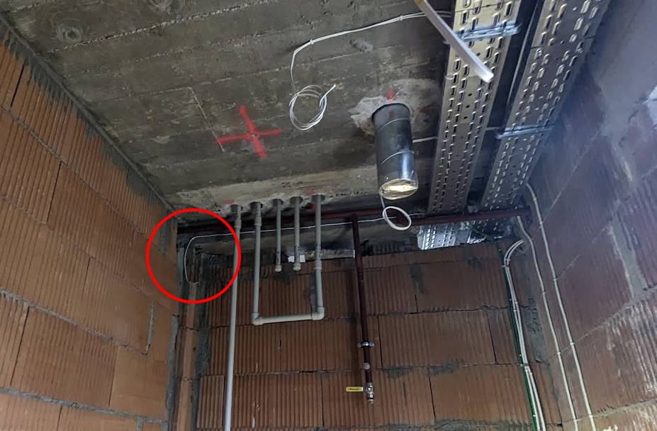
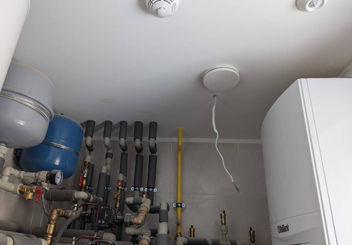
Luckily, I’ve also made a second mistake, during the design of the lights in the room - equipped with absolutely zero information of how the equipment will be installed, I thought a second lamp above the equipment would be of any use. Surprise! Half of the room’s volume is piping, boilers, water tanks and so on - so I just have a lone 230V cable hanging from the ceiling. Perfect for powering a hard wired motion sensor!
Selecting the sensor, I had three requirements:
- It shouldn’t be outrageously expensive - after all it’s just something to turn on the lights when I want to wash my hands after working in the garage.
- It must either run on Zigbee, in a way that does not break the network, or run open-source firmware, so that I am confident it’s sufficiently secure.
- It must be trivial to install it in the suspended ceiling.
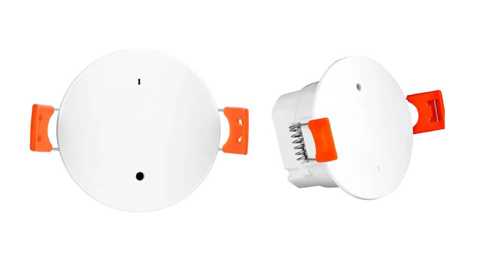
Despite having built custom mmWave ESPHome sensors (which will be covered in another post), I didn’t feel like putting a “custom” 230V to 5V power supply in the ceiling. After some research, I selected the $20-ish Tuya ZY-M100-5.8G series - it both satisfied the Zigbee support requirement (albeit with some caveats) and in theory it was easy to replace the Tuya Zigbee module with an ESP-12F.
After receiving the unit, I immediately opened it up to evaluate the second option - replacing the Zigbee module with an unlocked Wi-Fi one. Despite the apparent existence of some firmware fixing spammy Zigbee behaviour, I didn’t want to risk my 100+ devices becoming unreliable - and since I’m using ZHA, the ZY-M100 quirks were not implemented at the time I made the decision to flash it.
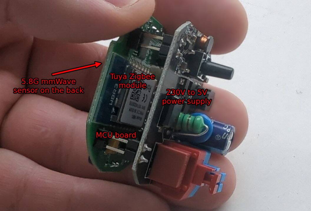
A quick Google search got me onto the ESPHome devices repository, where someone claimed that replacing the Tuya WiFi module with an ESP-12F-compatible chip (ESP32-C3 one per their writeup) would be trivial, other than having to connect EN to 3V3. I ended up buying the following items on Amazon:
For any further disassembly, I applied flux and leaded solder to the joints I wanted to remove, diluting the RoHS-compliant lead-free solder. This gets the melting temperature low enough that I can safely apply hot air to the module without damaging the rest of the components’ joints.
The 230V-5V PSU PCB is attached to the MCU board with four 2 pin headers:
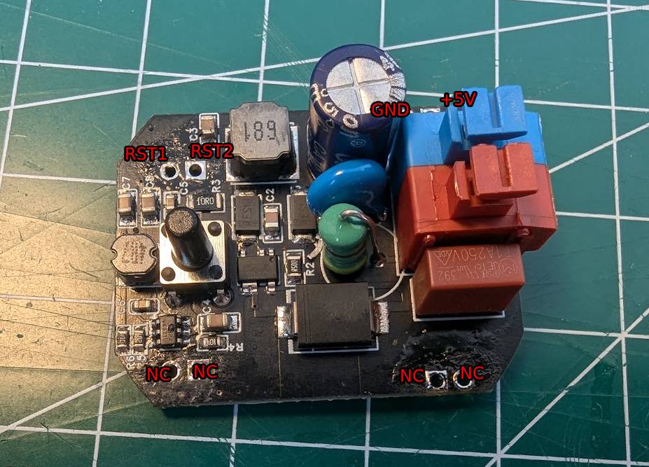
I used the Engineer SS-02 solder sucker to clean the through holes. Despite removing most of the solder, I then had to use a tiny, flat screwdriver to detach the pins from the vias. Do not worry if the non-connected PSU vias split from the PCB’s substrate - there is no copper pour holding them in place, so they are very fragile. Make sure to not bend the pins when pulling the PCBs apart.
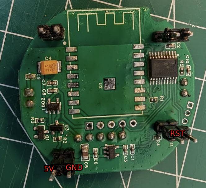
The MCU board has a simple layout with a 5V to 3.3V LDO and what appears to be a reset circuit implemented through cutting off power. For any further testing, I replaced the PSU board with a lab power supply feeding 5V into DuPont female jumper cables, so as not to have to deal with 230V sitting on my test bench.
The stock WBR3 module… wasn’t a Zigbee one? Lovely. Yet another reason to replace it! Per the spec sheet:
- The module is enabled by default, unless
ENis pulled high. - Pin 1 (
RST) is not connected.
There are no further requirements to get the module running. As you will soon see, this is most likely different to the module you’d want to replace it with.
Removing the Wi-Fi module is very simple with a hot air station. Apply thick flux, leaded solder to the pins to decrease their melting point, and heat up both rows of the castellated pins by alternating application of the hot air between them. Eventually you should be able to slide the module off the MCU board. Do not use any significant amounts of force, or you’ll strip the pads off the board. After you remove the module, use a solder wick to clean up the pads.
Afterwards, I used the breakout board, put the ESP-12F module against the pins and flashed the ESPHome firmware. I had to make a couple changes compared to the ESPHome device repository config - namely switch to the ESP8266 platform, disable UART logging and change the pins. Here’s my config:
substitutions:
  device_ssid: "Tuya Motion Sensor"
  device_name: boiler-motion-sensor
  device_description: "Tuya ZY-M100 Human Prescence Sensor ESP-12F ESP-IDF"
  friendly_name: "Boiler Motion Sensor"
  main_device_id: "boiler-motion-sensor" # Put the name that you want to see in Home Assistant.
  project_name: "tuya.zy-m100-wifi-esp-idf"
  project_version: "1.0"

esphome:
  name: ${device_name}
  comment: ${device_description}
  platformio_options:
    board_build.flash_mode: dio
  project:
    name: "${project_name}"
    version: "${project_version}"

esp8266:
  board: d1_mini

api:
  password: "your-ha-api-password"

logger:
  baud_rate: 0

web_server:
  port: 80

ota:
  - platform: esphome
    password: ""

wifi:
  ssid: "your-wifi-network"
  password: "your-wifi-password"
  power_save_mode: none
  ap:
    ssid: ${device_ssid}
    password: "your-fallback-ap-password"

uart:
  rx_pin: GPIO3
  tx_pin: GPIO1
  baud_rate: 115200

# Register the Tuya MCU connection
tuya:

sensor:
  # WiFi Signal sensor.
  - platform: wifi_signal
    name: ${friendly_name} Signal strength
    update_interval: 60s
    internal: true
  # Uptime Sensor
  - platform: uptime
    name: "${friendly_name} Uptime"
    id: uptime_sensor
    update_interval: 360s
    on_raw_value:
      then:
        - text_sensor.template.publish:
            id: uptime_human
            state: !lambda |-
              int seconds = round(id(uptime_sensor).raw_state);
              int days = seconds / (24 * 3600);
              seconds = seconds % (24 * 3600);
              int hours = seconds / 3600;
              seconds = seconds % 3600;
              int minutes = seconds /  60;
              seconds = seconds % 60;
              return (
                (days ? to_string(days) + "d " : "") +
                (hours ? to_string(hours) + "h " : "") +
                (minutes ? to_string(minutes) + "m " : "") +
                (to_string(seconds) + "s")
              ).c_str();
    # Light Sensor
  - platform: tuya
    name: "${friendly_name} Light Intensity"
    id: light_intensity
    sensor_datapoint: 104
    unit_of_measurement: "lux"
    icon: "mdi:brightness-5"
    device_class: "illuminance"
    state_class: "measurement"
    # Distance from Detected Object
  - platform: "tuya"
    name: "${friendly_name} Target Distance"
    id: target_distance
    sensor_datapoint: 9
    unit_of_measurement: "cm"
    icon: "mdi:eye"
    device_class: "distance"
    state_class: "measurement"

text_sensor:
  # Expose WiFi information as sensors.
  - platform: wifi_info
    ip_address:
      name: ${friendly_name} IP
    ssid:
      name: ${friendly_name} SSID
    bssid:
      name: ${friendly_name} BSSID
  # Expose Uptime
  - platform: template
    name: ${friendly_name} Uptime Human Readable
    id: uptime_human
    icon: mdi:clock-start

# Restart Buttons
button:
  - platform: restart
    id: "restart_device"
    name: "${friendly_name} Restart"
    entity_category: "diagnostic"
  - platform: safe_mode
    id: "restart_device_safe_mode"
    name: "${friendly_name} Restart (Safe Mode)"
    entity_category: "diagnostic"
number:
    # Sensitivity
  - platform: "tuya"
    name: "${friendly_name} Sensitivity"
    number_datapoint: 2
    min_value: 0
    max_value: 9
    step: 1
    icon: "mdi:ray-vertex"
    # Min Detection Distance
  - platform: "tuya"
    name: "${friendly_name} Near Detection"
    number_datapoint: 3
    min_value: 0
    max_value: 1000
    step: 1
    mode: slider
    unit_of_measurement: "cm"
    icon: "mdi:signal-distance-variant"
    # Max Detection Distance
  - platform: "tuya"
    name: "${friendly_name} Far Detection"
    number_datapoint: 4
    min_value: 0
    max_value: 1000
    step: 1
    mode: slider
    unit_of_measurement: "cm"
    icon: "mdi:signal-distance-variant"
    # Detection Delay
  - platform: "tuya"
    name: "${friendly_name} Detection Delay"
    number_datapoint: 101
    min_value: 0
    max_value: 100
    step: 1
    unit_of_measurement: "s"
    mode: slider
    icon: "mdi:clock"
    # Fading Time - Cool Down Period
  - platform: "tuya"
    name: "${friendly_name} Fading Time"
    number_datapoint: 102
    min_value: 0
    max_value: 1500
    step: 1
    unit_of_measurement: "s"
    mode: slider
    icon: "mdi:clock"

select:
    # Self Check Enum
  - platform: "tuya"
    name: "${friendly_name} Self Check Result"
    icon: mdi:eye
    enum_datapoint: 6
    options:
      0: Checking
      1: Check Success
      2: Check Failure
      3: Others
      4: Comm Fault
      5: Radar Fault

binary_sensor:
    # Status
  - platform: status
    name: "${friendly_name} Status"
    # Occupancy Binary Sensor
  - platform: "tuya"
    name: "${friendly_name} Presence State"
    sensor_datapoint: 1
    device_class: occupancy
I confirmed that the firmware was working by watching the DHCP IP tables in my router and connecting to the web UI. Afterwards I applied more flux to the MCU board and soldered the new module in place. This was trivial as the backing ground pour is not present in the 12F.
Having missed the note about connecting EN to VCC, I ran into an issue - the PCB still didn’t boot, despite technically having the same layout. Since the activity LED was not blinking, it was quite obvious that it wasn’t enabled. I went to the ESP-12F’s spec sheet and l found out the following tables:
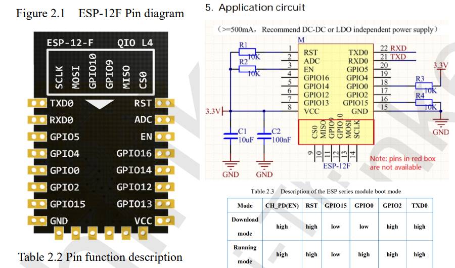
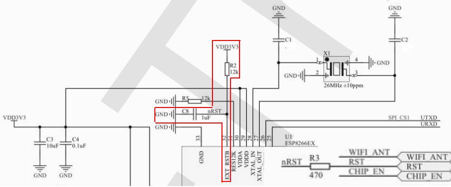
By going by each pin from the boot mode table, probing it and analyzing the schematic we can conclude that:
ENshould be pulled high by connecting it toVCCwith a 10K resistor.RSTshould be pulled high - and it already is inside of the ESP-12F module through a 12K resistor.GPIO0should be pulled high with an additional 10K resistor.GPIO15should be pulled high with yet another 10K resistor.
I skipped TXD0, as it was connected to other circuitry on the Tuya MCU board - it worked fine without it. The PCB with all the required 10K resistors looks like this:
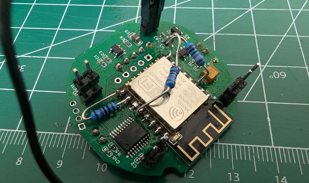
After connecting 5V and GND to the MCU PCB the module successfully booted! I reassembled the sensor, mounted it in the desired place, fine tuned it in the desired place.
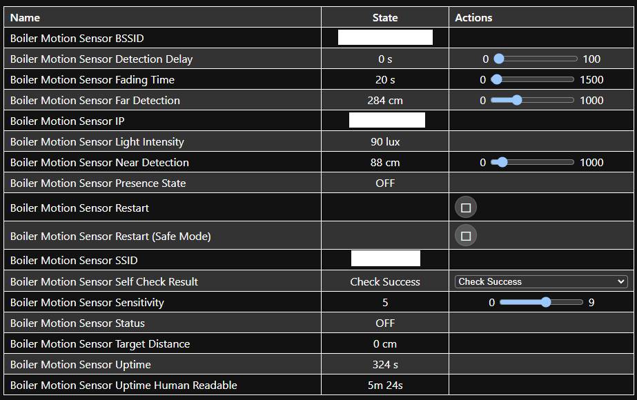
Automating it in Home Assistant was as simple as adding the device and linking the light’s state to the presence state entity.
- id: 'motion_boiiler_room'
  alias: 'Motion in the boiler room turns on the ceiling light'
  description: ''
  use_blueprint:
    path: homeassistant/motion_light.yaml
    input:
      motion_entity: binary_sensor.boiler_motion_sensor_presence_state
      light_target:
        entity_id:
          - light.boiler_room_light
      no_motion_wait: 5
Happy automating!
Author: @pzduniak